Drilling Caravelle Arms Brass Grip Frame for NM Blackhawk

Help Support Ruger Forum:

Bruce757

Bearcat
Joined
Jan 16, 2016
Messages
7
Howdy folks,

I've been lurking these forums for quite some and have benefited immensely from some of the info that the regulars on here post. So first and foremost, thank you.

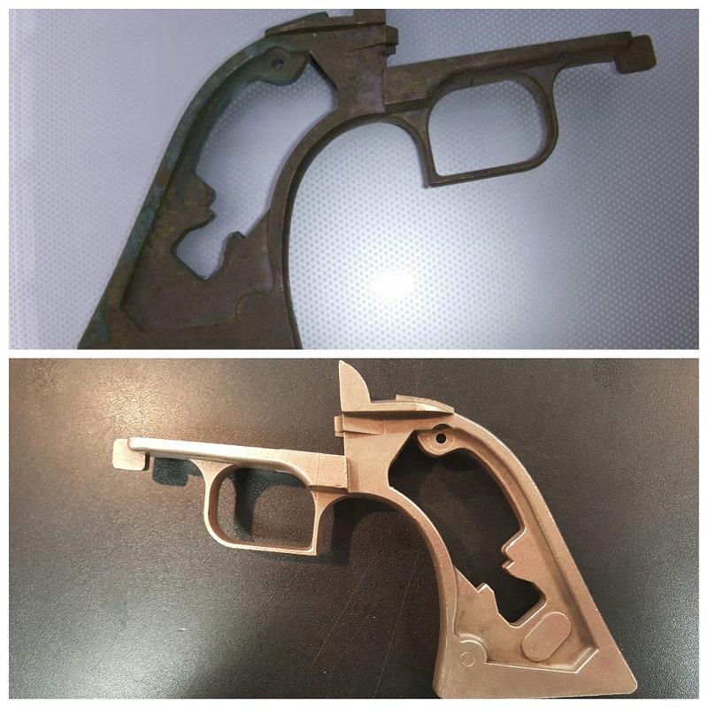
Secondly, I am posting because I have recently acquired a Caravelle Arms Brass Grip Frame for my Convertible .357 NM Blackhawk. The grip frame I purchased has never been used or even drilled for that matter. I reached out to local gunsmiths and the two that I spoke with both said it was beyond their capabilities. Can anybody on here recommend somebody that would be proficient in the this aspect of gunsmithing? I was told by one of the local smiths here that this falls into the realm of CNC machinery and that I would need to find somebody that is experienced with CNC.

Here is a link for the frame. http://www.ebay.com/itm/351629011771

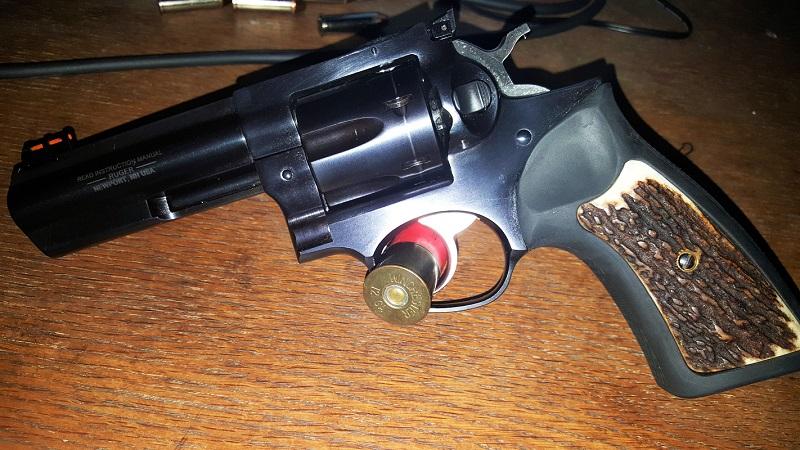
And here is my Convertible NM Blackhawk with custom aged oak grip panels.


I am also adding a power custom Bisley Trigger and Hammer with wolff springs, an oversized cylinder latch, a free spin pawl and a steel ejector rod housing.

I feel that I am competent enough to knock out the majority of this project on my own, however, it is all riding on whether or not I can get this Brass Grip Frame drilled properly. If anybody has any knowledge or recommendations to offer, I'd greatly appreciate it. Thanks!
 

roylt

Hunter
Joined
Sep 21, 2010
Messages
3,109
I am a cheap azz so IF I really wanted brass I would try to drill it myself. You can measure the frame you already have and go from there.

I'm sure others will have better advise.

Welcome to the forum.
 

Chuck 100 yd

Hunter
Joined
Mar 20, 2010
Messages
3,251
Location
Ridgefield WA
Set up and transferring hole locations would require real precision to make me happy. God luck. Don't let go of your old grip frame until it is done!
 

Hondo44

Hawkeye
Joined
Apr 3, 2009
Messages
8,057
Location
People's Republik of California
If you really have to have a brassie, you'll have more than a few bucks tied up and a wait time. In the long run, you'd be better off dollar wise and with less hassle by waiting to find/buy a Ruger brassie.

I would also consider a SBH steel grip frame heavily brass plated to keep cost much lower. You won't wear the plating in your lifetime. Or even a stainless steel grip frame for a non-tarnishing and non-smelly alternative.

Unless you clear coat the brass or if you like the dirty tarnished look, be prepared to have your hands stink like tarnished brass, especially when sweaty in the summer time. Just some thoughts and feedback from my "customers" who would do something different next time.

Not trying to tell you what to do, it's your gun and I think people should do what they want. Just some alternative suggestions to think about.

I would also forget about the oversize cyl latch.

FROM MY RUGER TUTORIAL: Oversize/extra tight cylinder pin and/or cyl latches.

This may be counter intuitive, but tight lock up is not always a good thing in a production level revolver.

Extra tight cylinder lock up and oversize cyl pins can lead to accuracy issues in a mass produced, non-line bored, non-super precision custom revolver.

Standard production revolvers are designed with a little cylinder play. The cylinder latch allows a few thousandths of + and - side play while the base pin is a bit loose and allows a couple of thousandths horizontal and vertical play.

When a round is fired, this play allows the cylinder to move a tiny bit to self align with the bore as the ogive of the bullet enters the forcing cone, another important feature. Replacing the base pin with a tight custom pin or the latch with an oversize latch when not needed for wear, can eliminate the cylinder's ability to self align with the barrel bore and one reason the forcing cone was designed, it's part of the nifty design.

Tight cyl lock up is usually caused by a slightly too long 2nd tooth of the cyl pawl. Fortunately a few careful file strokes will remedy this.

Therefore tight cylinder lock up/cyl pawl, and/or installing extra tight pins and latches can reduce accuracy in production revolvers.
 

Bruce757

Bearcat
Joined
Jan 16, 2016
Messages
7
Hondo44 said:
If you really have to have a brassie, you'll have more than a few bucks tied up and a wait time. In the long run, you'd be better off dollar wise and with less hassle by waiting to find/buy a Ruger brassie.

I would also consider a SBH steel grip frame heavily brass plated to keep cost much lower. You won't wear the plating in your lifetime. Or even a stainless steel grip frame for a non-tarnishing and non-smelly alternative.

Unless you clear coat the brass or if you like the dirty tarnished look, be prepared to have your hands stink like tarnished brass, especially when sweaty in the summer time. Just some thoughts and feedback from my "customers" who would do something different next time.

Not trying to tell you what to do, it's your gun and I think people should do what they want. Just some alternative suggestions to think about.

I would also forget about the oversize cyl latch.

FROM MY RUGER TUTORIAL: Oversize/extra tight cylinder pin and/or cyl latches.

This may be counter intuitive, but tight lock up is not always a good thing in a production level revolver.

Extra tight cylinder lock up and oversize cyl pins can lead to accuracy issues in a mass produced, non-line bored, non-super precision custom revolver.

Standard production revolvers are designed with a little cylinder play. The cylinder latch allows a few thousandths of + and - side play while the base pin is a bit loose and allows a couple of thousandths horizontal and vertical play.

When a round is fired, this play allows the cylinder to move a tiny bit to self align with the bore as the ogive of the bullet enters the forcing cone, another important feature. Replacing the base pin with a tight custom pin or the latch with an oversize latch when not needed for wear, can eliminate the cylinder's ability to self align with the barrel bore and one reason the forcing cone was designed, it's part of the nifty design.

Tight cyl lock up is usually caused by a slightly too long 2nd tooth of the cyl pawl. Fortunately a few careful file strokes will remedy this.

Therefore tight cylinder lock up/cyl pawl, and/or installing extra tight pins and latches can reduce accuracy in production revolvers.

Wow, great info regarding the cylinder latch. I'll definitely hold off on that. I was looking to restore the brass via polishing and cleaning before clear coating to avoid the aforementioned smell and upkeep issues. A lot of folks have suggested getting the aluminum alloy frame I have Cerakoted gold/brass to save myself time and money. I like the steel sbh option but have already purchased this Caravelle grip frame. The dragoon style trigger guard is really growing on me too. I have access to a drill press, I might just give it a go since I can't find a gunsmith in Virginia Beach that's bold/equipped enough to tackle this.
 

bnewberry

Single-Sixer
Joined
Jun 17, 2008
Messages
227
Location
MICHIGAN
I did one of these several years ago using just a vise and a drill press. It works but it does not look as good as I would like it to. Good luck if you proceed! Measure carefully and go slow!
 

Hondo44

Hawkeye
Joined
Apr 3, 2009
Messages
8,057
Location
People's Republik of California
You'll probably do just fine drilling the frame yourself. Measuring the location of the screw holes can be tricky to get precise. By using two old Ruger frame screws shortened and with the heads turned down to two points, one on either side of the slot; or ground down to a point with a Dremel tool while spinning them in your drill press, is a way to transfer the proper hole locations to the brass grip frame.

Screw them almost flush into the two cyl frame trigger guard holes using a small screwdriver in what's left of the screwdriver slot. Place the grip frame in place over the screws and tap the grip frame to make a mark. Drill and countersink those two holes first. Then put the two pointy screws in the two holes beside the hammer. Screw the grip frame on using the trigger guard holes/screws. Tap the ears to make a mark. Drill those two holes, screw the grip frame on with the four screws, and do the hole in front of the trigger guard last. Good luck and have fun.

Just FYI, if you retain the alloy grip frame, I wouldn't cerakote it brass color, it can be plated with actual brass over a copper plate. No more expensive and it'll look like real brass because it is.
 

Bruce757

Bearcat
Joined
Jan 16, 2016
Messages
7
Hondo44 said:
You'll probably do just fine drilling the frame yourself. Measuring the location of the screw holes can be tricky to get precise. By using two old Ruger frame screws shortened and with the heads turned down to two points, one on either side of the slot; or ground down to a point with a Dremel tool while spinning them in your drill press, is a way to transfer the proper hole locations to the brass grip frame.

Screw them almost flush into the two cyl frame trigger guard holes using a small screwdriver in what's left of the screwdriver slot. Place the grip frame in place over the screws and tap the grip frame to make a mark. Drill and countersink those two holes first. Then put the two pointy screws in the two holes beside the hammer. Screw the grip frame on using the trigger guard holes/screws. Tap the ears to make a mark. Drill those two holes, screw the grip frame on with the four screws, and do the hole in front of the trigger guard last. Good luck and have fun.

Just FYI, if you retain the alloy grip frame, I wouldn't cerakote it brass color, it can be plated with actual brass over a copper plate. No more expensive and it'll look like real brass because it is.

Thank you again for sharing your insight. This is exactly the kind of help I was looking for. I've been working my fingers to the bone cleaning the tarnish off of the grip frame and am surprised to learn that Ketchup makes an excellent brass cleaner. I've screen shotted your post and will be giving the marking and drilling a shot soon.
 

Bruce757

Bearcat
Joined
Jan 16, 2016
Messages
7
For those interested,

966DOqI.jpg


The top photo is the shape I received the grip in.

The bottom photo is after letting it soak in a homemade ketchup, vinegar and lemon juice mix. I scuffed it up with some steel wool to see if I could get more of a yellow shine out of it as opposed to the dull look.

Might even scuff it up some more with some 300 grit and then work into a polish with some 2000 grit. Also considering going to the hardware store to look at brass polishes.
 

Bruce757

Bearcat
Joined
Jan 16, 2016
Messages
7
Jimbo357mag said:
A fine home gunsmithing project. Good luck. :D

Thanks, Jimbo! I hope to be posting more photos once the project is complete. This will be my second Ruger .357 project.

Last year I fiddled around with a gp100 . Here's a shot even though she's dirty.

y3OACKw.jpg
 

Aeroscout9

Single-Sixer
Joined
Sep 7, 2008
Messages
220
I've got one of these too. Before it can be drilled for the mounting screws, it'll need some brass removed from the portion of the frame that meets the underside of the cylinder frame. Notice how thick the gf is up top where the trigger goes through. The look at an OEM gf and see how thin they are. These brassies aren't finish machined in more spots than just the gf screw holes! It'll be a project to finish on. I'm working on one but going slow so I don't Botch the whole thing.
 

Hondo44

Hawkeye
Joined
Apr 3, 2009
Messages
8,057
Location
People's Republik of California
The trigger guard strap thickness even on Ruger grip frames can vary quite a bit especially among different vintage Rugers.

The determining factors are: If the ears on the grip frame are tall enough to reach the top edge of the cyl frame surface and the extensions on the grip frame are high enough to go into the milled recesses of the cyl frame, there's no need to remove material from the top surface of the trigger guard.
 

SAJohn

Hunter
Joined
Jan 6, 2007
Messages
2,300
Location
Terrebonne, Oregon, USA
Hondo, A big thank you. I have been faced with the same problem and was trying to make up some sort of jig. You solution to the problem is elegant and simpler.

John
 

Aeroscout9

Single-Sixer
Joined
Sep 7, 2008
Messages
220
I agree with Mr. Honda but if you look at your casting, it's clear that the machining process to mate it to a gripframe would remove material from the top of the gf where it meets the bottom of cylinder frame. It may work without doing that though and would depend on where the ears meet the frame. I'm going slow and will post results at a later time.
 

Chuck 100 yd

Hunter
Joined
Mar 20, 2010
Messages
3,251
Location
Ridgefield WA
Here is how I would set up to drill those holes in the grip frame.
Strip all internal parts from the main frame.
Fit the grip frame to the rear and bottom of the main frame to a very close fit.
Mount the main frame in the drill press vice so that a tap size drill will easily pass through one of the holes in the main frame. This will require blocks and shims as the main frame has no parallel sides. Clamp the vise solidly to the drill press table and recheck that the drill slides down through the hole without side thrust of any kind.
Now temporarily super glue the grip frame to the main frame and let dry.
Install a center drill in the drill press and spot your hole.
Next install the tap size drill again and drill the hole.
A clearance drill then will open the hole for the screw.being careful not to cut into the main frame.
A counter bore from Brownells is the proper tool to countersink for the screw heads.
Heat from a heat gun or propane torch will break the super glue's bond far below any temperature that will affect the heat treating.

Repeat the above for the rest of the holes. After a couple holes are done the super glue is no longer needed,the screws will hold the grip frame.
Extremely accurate transfer of holes can be done in this manner.
 

Hondo44

Hawkeye
Joined
Apr 3, 2009
Messages
8,057
Location
People's Republik of California
Chuck,

I like your approach, it's first class; essentially making a jig out of the cyl frame. I'd likely go thru all that set up if I were doing more than one grip frame. Actually in fact I'd use a law enforcement destroyed cyl frame (cheap on all the auction sites) as a jig to just drill thru the cyl frame screw holes, and install hardened drill guides on the back end of the holes for drilling the grip frame pilot holes.

But too much set up time investment, for me at least, just for a one off.

Ruger grip frame screws are all the same; they are fillister head machine screws with a tapered seat. The 'clearance hole' size is the only uniqueness of the lower front GF screw. It's ~ .005" larger than the other four holes of the grip frame, giving it more play to align the sides of the trigger guard to the cyl frame. The counterbored hole is the same size as the other four.

So you don't want a standard counterbore for any of the grip frame holes.
 

Chuck 100 yd

Hunter
Joined
Mar 20, 2010
Messages
3,251
Location
Ridgefield WA
Hondo , you are right about the screw head and counter sink, what was I thinking? I think I would still use my Brownells counter bore just because it has a pilot and does a very neat job of it. I would grind a drill to the proper angle and add the taper to the hole as a final step.
This method would be very time consuming but if this project is for a hobby and not for profit, who cares?
I often spend 50-60 hours + making one Bowie knife,aiming for the highest quality I can possibly do.
 
Top