5-Shot Conversion - Documented

Help Support Ruger Forum:

Lee Martin

Hunter
Joined
Dec 18, 2002
Messages
2,313
Location
Arlington, Virginia


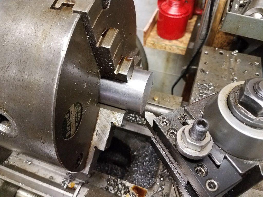
The rough turned stainless is cut 2.20" in length using an electric hacksaw.


Next I faced both ends in our Colchester lathe:


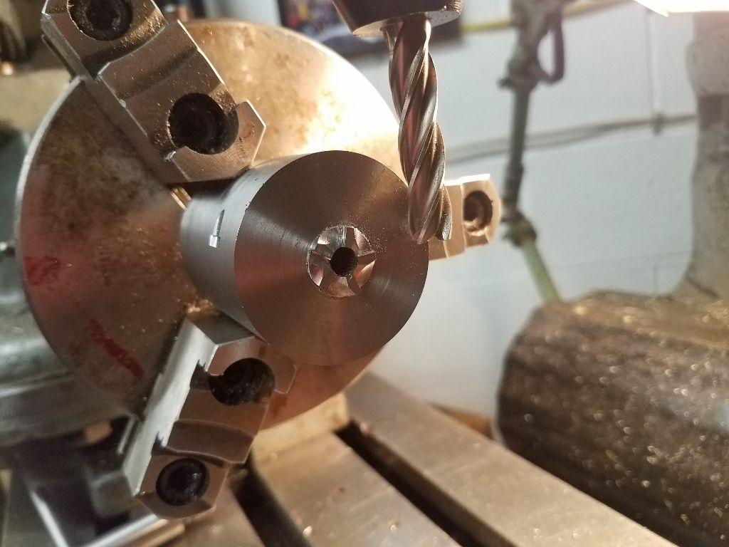
The basepin hole is drilled, first by spotting one end. This is followed by 1/8" and 15/64" drill bits.


A 0.248" reamer finishes the hole. After heat treating, I'll hone it to 0.250".


Using a mandrel, I put the cylinder between centers for outside turning. This ensures the outer diameter is concentric to the basepin hole. Final o.d. is 1.810".


Lee Martin

Hunter
Joined
Dec 18, 2002
Messages
2,313
Location
Arlington, Virginia


A Woodruff key cutter makes the bolt stops. Since I'm starting to do cylinders, I ordered a second. These come 1/8" wide and 1/2" in diameter. Clearly too thick for a 0.0960" notch. It has to be ground in a tool and cutter grinder.


Post-grinding:


Before milling the stops, I machined the ratchet boss 0.585" in diameter. Standard Ruger ratchet height is 0.150". Mine will be shorter since I'm recessing the cylinder. 500 Linebaugh rims mic 0.060", making the target height 0.090".


I'll now share some of the geometry involved in action timing. First, the cylinder is chucked in a horizontal indexing head and a mandrel is inserted. The key cutter is brought down to touch the top of the mandrel. The table is then raised 0.215".


Math time. The stops on a Ruger are 0.704" in from the rear edge of the ratchet. My cutter measures 0.514" in diameter. That means the table is moved 0.961" from the back edge (0.704 + (0.514/2)). The cutter is cross fed until it touches the cylinder and our digital readout is zeroed on the Y-axis.


The cutter is slowly fed in to a depth of 0.060". Dividing heads yield 9 degrees of rotation for one turn on the dial. The next notch, which is 72 degrees from the first, is positioned with 8 turns.


The next four stops are milled by repeating the above. Depth is monitored on our digital readout.


The bolt leads are done with a 3/8" endmill. Do not allow the endmill to reach the bottom edge of the notch. Otherwise, we'd lose our tight fit. Remember, the difference between my bolt and the stop is a miniscule 0.0008". A depth stop is set to ensure we go no lower than the middle of the notch.
 

Lee Martin

Hunter
Joined
Dec 18, 2002
Messages
2,313
Location
Arlington, Virginia


A large wheel cutter is how we 'gear' the ratchet. But we can't do a straight cut; the geometry dictates these be offset 20 degrees to the rear plane. The indexing head is canted 20 degrees out from the x-axis. The mandrel is reinserted in the basepin hole and the cutter is brought up to touch the bottom edge. Drop the table 0.090".


Now here's the trick to timing the ratchet relative to the notches. Dividing heads have a 40:1 ratio between handle rotation and spindle rotation. Turn the handle 40 times and the spindle moves 360 degrees. Hence, one turn equals 9 degrees.

The ratchet's teeth have to be offset within a narrow range of degrees from the position of the bolt stop. Our indexing head is rotated 1 and 24/57 turns (~12.8). The cutter is zeroed on the back edge of the ratchet. IMPORTANT – the zeroing occurs on the outer most edge of the circumference. Once that's done, the wheel is fed into a depth of 0.060".


To cut the next cog, the indexing head is turned 8 rotations. This is one of the most precarious steps in making a cylinder. If the ratchet depth and position relative to the notches are off, we're screwed. An error here sends it to the scrap pile.


We're not quite done with the ratchet. Next time, I'll mill relief cuts in between the cogs.
 

VernTMG

Single-Sixer
Joined
Aug 30, 2009
Messages
290
Location
Glendale, Az.
This is some seriously cool work, I'm enjoying every part of it. So thanks and can you work faster so you can post more haha. Fun to watch the progress Thanks
 
Joined
Apr 2, 2014
Messages
3,284
If it's ok I've got two questions.
What alloy is the cylinder out of?
And not knowing Ruger single actions I'm
guessing the bolt notches are offset .043
from the basepin centerline?
Thanks
Dave
 

Lee Martin

Hunter
Joined
Dec 18, 2002
Messages
2,313
Location
Arlington, Virginia


The space between each ratchet cog must be relieved. I'll get into why and the specific geometry when I cover pawl modification. But in short, these cuts allow the hand's second leg to clear the ratchet. If left un-milled, the lower portion can get wedged against the pawl slot.

A standard 3/8" endmill relieves the ratchet. I zeroed it against each plane before feeding in 0.060". The cutter was moved along the Y-axis as opposed to the X. This is repeated by advancing the indexing head 8 times to locate the next cog.


Lee Martin

Hunter
Joined
Dec 18, 2002
Messages
2,313
Location
Arlington, Virginia


Total cylinder length must be tightly managed. Cut it too short and you'll have endshake. If that happens, install a press fit bushing machined a few thousandths long. Then slowly grind or lathe in half-thousandth increments until it fits. Or if you have a surface grinder, dial to ten-thousandths for an exact match. You're close if the cylinder goes in under force but drags when cycled. A few tenths more and it should freely spin with no shake.

I begin by torqueing a spud into the front of the frame. This counteracts dimensional changes that took place when opening the window. That sounds odd so let me explain. When steel is milled, work hardening occurs. Under these conditions, the frame can contract a thousandth or two. We found this out the hard way on my Buffalo Seville. The heat treated cylinder was dead rigid until the barrel was installed. That actually re-sprung the frame 0.0015", probably by way of stress relieving. 0.0015" is acceptable endshake for a factory gun, but not on our customs. We bushed the gas ring and ground the face, thus eliminating discernable play.


The inside of the frame is measured with instrumentation accurate to tenths.


From the back of the ratchet recess to the gas ring boss equals 1.982". The blank is 2.203", meaning I'll remove 0.221". A depth stop is set on the lathe table. Facing is done in increments of 0.030" down to 2.000". I then machined the gas ring 0.440" in diameter and to a height I knew would be too long.


Side shot of the gas ring cut tall:


I took extremely light cuts across the boss until it fit the frame. This is tedious and not a step you want to rush. 0.004" was turned off the back of the cylinder to prevent rub on the breech face. When the cylinder goes in smoothly and rotates without drag, I quit. Here's a shot of it in the frame using a spare basepin. Three things to highlight:

1) If you're OCD like I am, get used to superficial scuffs. The frame and cylinder go through a lot of machining and test fitting to get to this point. Once the gun is complete, I'll polish and buff each and every part.

2) A 0.004" feeler gauge barely goes between the rear cylinder and the recoil shield. Top and bottom clearance on the cylinder is 0.008" per side.

3) Barrel protrusion into the frame is 0.030" (minus 0.001" – 0.0015" for cylinder gap). I'm making use of the entire window.


RSIno1

Hunter
Joined
Sep 17, 2013
Messages
2,858
Location
Southern California
VernTMG said:
.....and can you work faster so you can post more haha......
I've got the tools but not that skill level. I'm thinking I'd have to at least triple the time then add some more for when I scraped a part and had to start over. I did an AR from a raw forging that took me just over 10 hours. I can do 80% ones in a little over an hour.
 

Lee Martin

Hunter
Joined
Dec 18, 2002
Messages
2,313
Location
Arlington, Virginia


We've now come to the most intricate part of the conversion – timing the gun. First, I reinstalled the guts to include the heavier gate spring by Power Custom.


Because the frame window was milled, the bolt height has to be shortened. With the gate open, the excess is marked with a scribe.


The bolt is secured in a vise and the height is reduced from 0.280" to 0.250".


The re-contoured bolt:


With 72 degree rotation between chambers, the bolt also has to drop faster. To accomplish this, the hammer plunger recess is filed back about 0.030". This allows it to protrude more from the hammer and the bolt is engaged sooner.


5-shots require reworking the pawl. I wish I could say there are standard dimensions here. You really have to alter them slowly, reinstall to test function, and remove metal to achieve correct timing. On a typical 5-shot build, we may test fit the pawl ten times to get it perfect.


Here are the main tenants of the modification:


The finished pawl:

 
Top